


About QUADOA® Optical CAD |
|---|
|
|
|
|
|
|
|---|
|
|
|
|
Multi-Sequential Raytracing |
|---|

|
|---|
| Create Multi-Path-Systems in the same model file. |
|
|---|
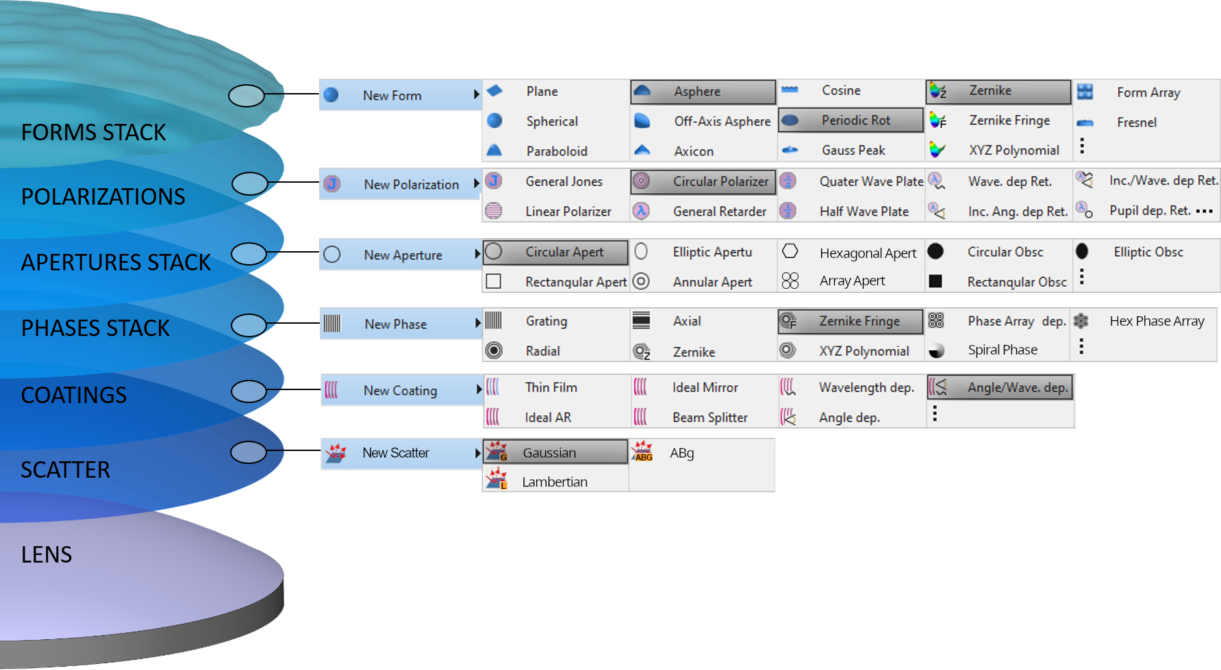
| Flexible Surface Type Definition thanks to the combination of surface properties with the QUADOA® Stack Ability. |
Flexible Surface Type Definition |
|---|
|
|
|---|
| Flexible Surface Type Definition thanks to the combination of surface properties with the QUADOA® Stack Ability. |
Powerful Optimization |
|---|
|
|---|
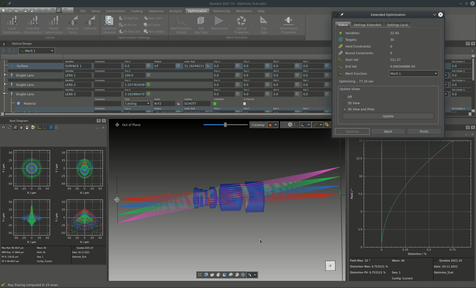
| Optimization of a Microscope Objective. |

|
|---|
| Object oriented approach with own coordinate system for each element for positioning and rotation. |
Modern Object-Based Architecture |
|---|
|
|
|---|
| Object oriented approach with own coordinate system for each element for positioning and rotation. |
Intuitive Design of Folded- and Off-Axis Systems |
|---|
|
|---|
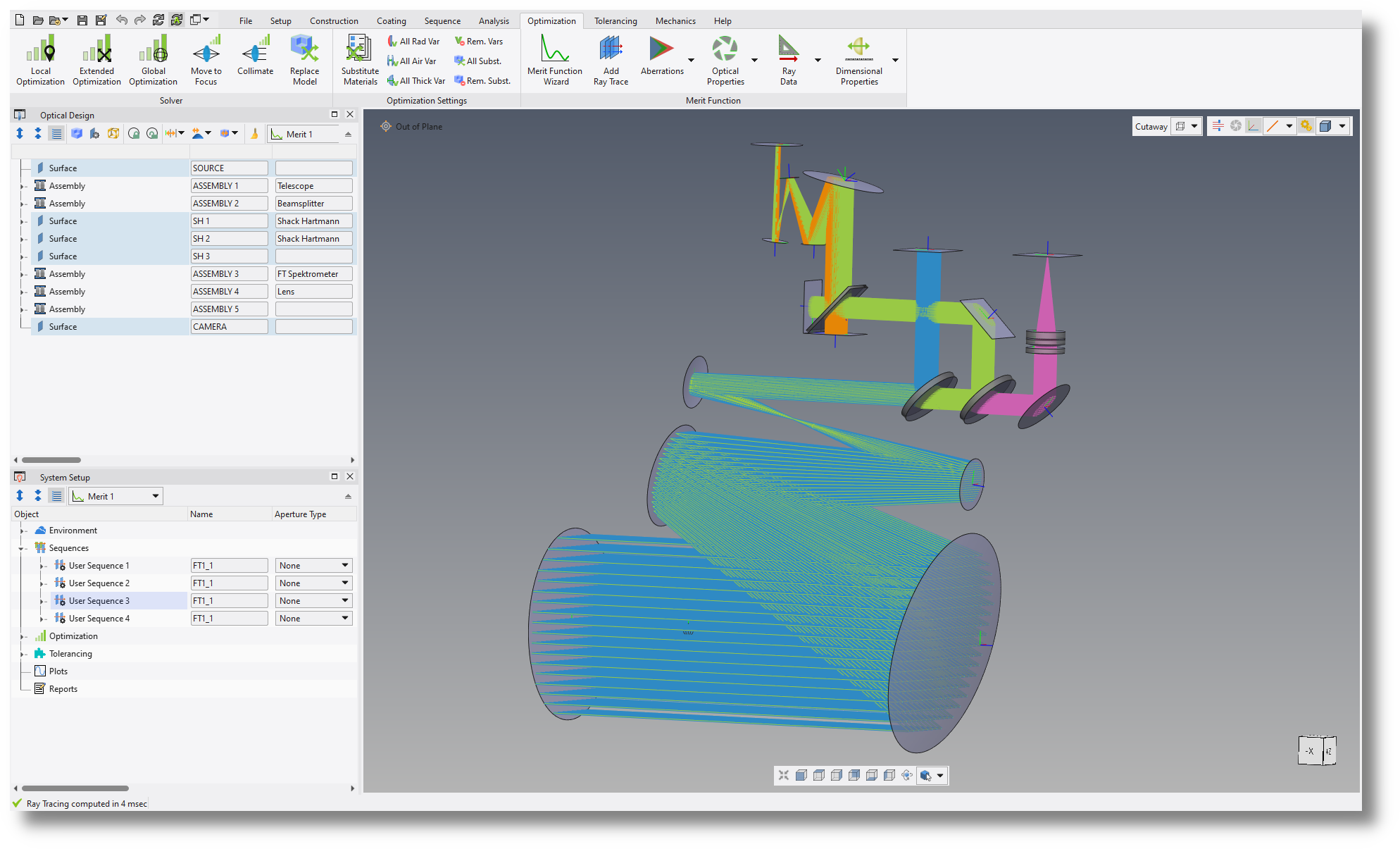
| Off-Axis Fourier Transform Spectrometer. |
|
|---|
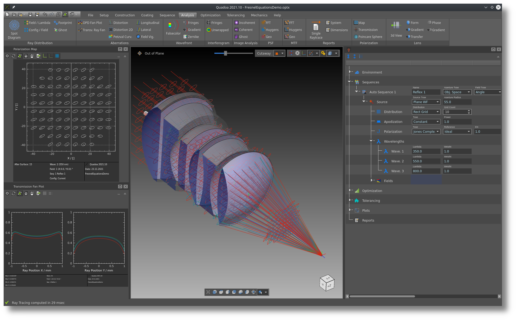
| Full polarization raytracing support. |
Polarization Raytracing |
|---|
|
|
|---|
| Full polarization raytracing support. |
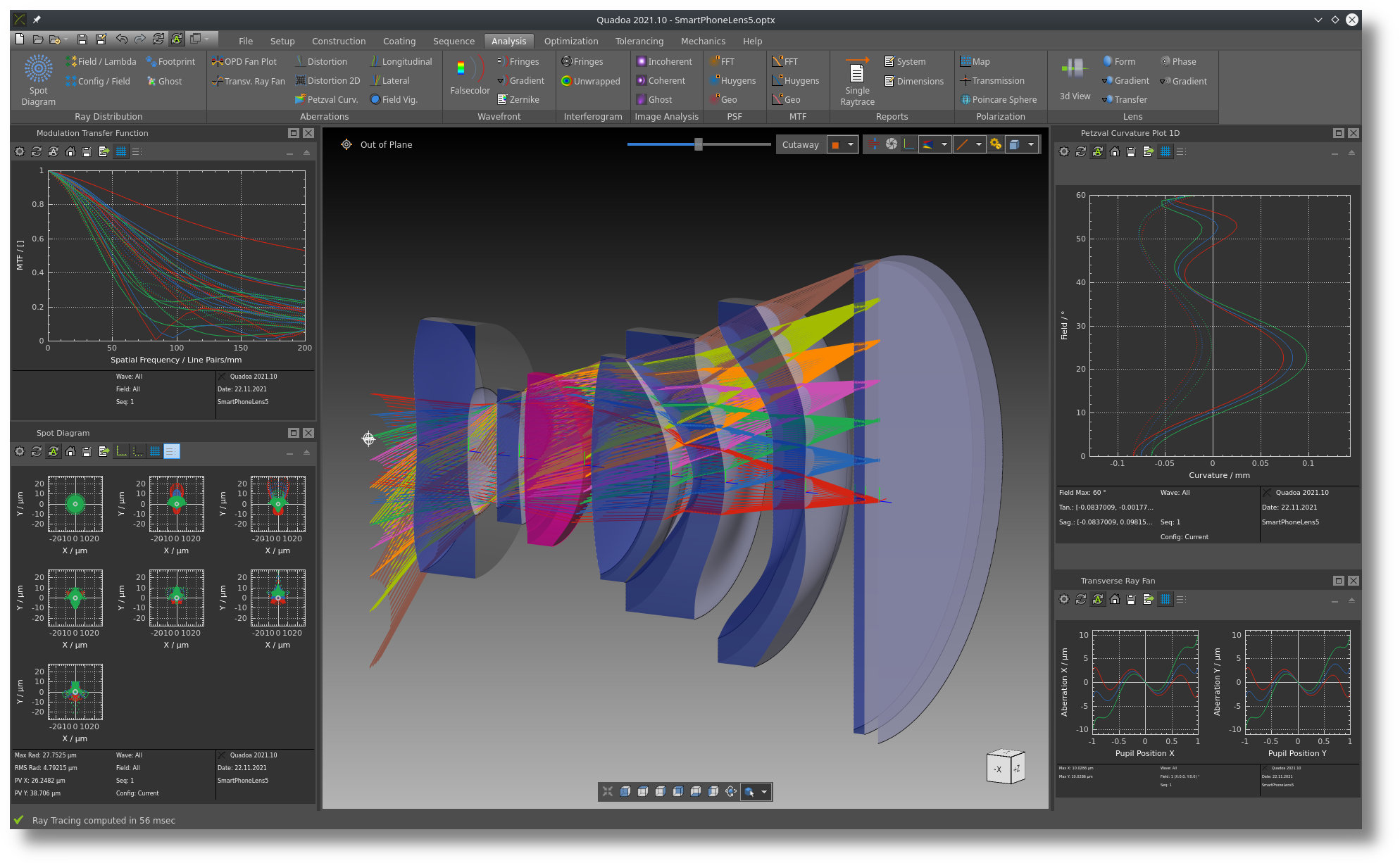
Wide Range of Analysis Features |
|---|

|
|---|
| The graphical User Interface (UI) enables an easy handling of even complex (e.g. folded) systems. |
|
|---|
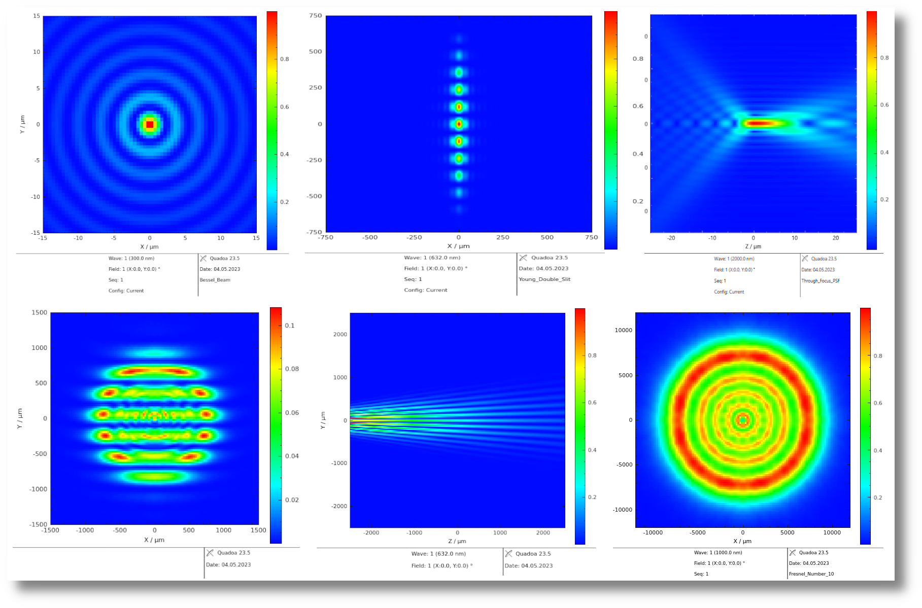
| Wave optics including beam propagation and fiber coupling. |
Wave Optics |
|---|
|
|
|---|
| Wave optics including beam propagation and fiber coupling. |
Bidirectional Exchange with Mechanical CAD |
|---|

|
|---|
| Import mechanical parts to QUADOA® Optical CAD and export mechanical parts from QUADOA® to mechanical CAD. |
|
|---|
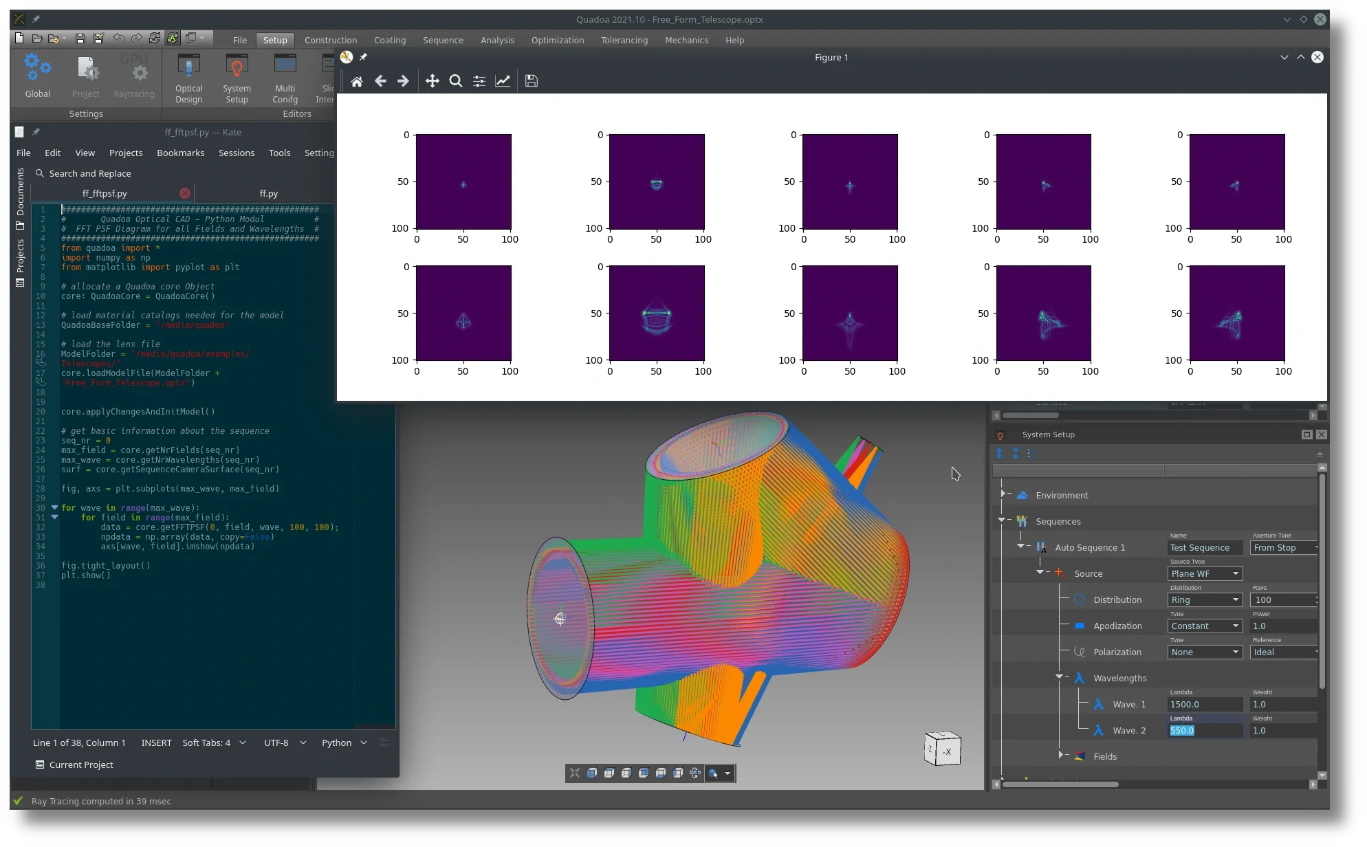
| Access to all core functions via the Scripting Interfaces for Python, MATLAB® and C++ SDK. |
Scripting Interfaces |
|---|
|
|
|---|
| Access to all core functions via the Scripting Interfaces for Python, MATLAB® and C++ SDK (available for Windows only). |
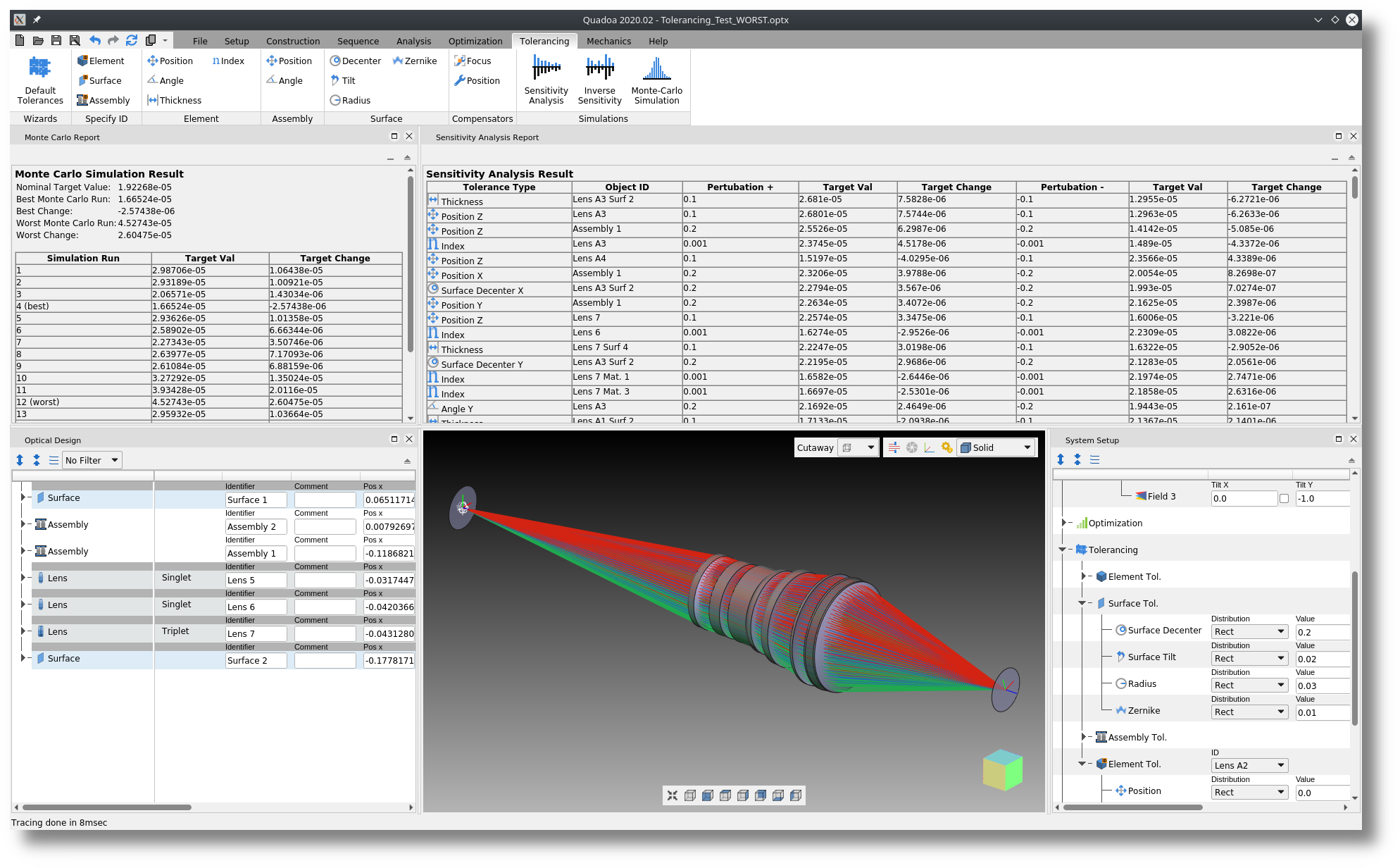
Real World Tolerance Analysis |
|---|
|
|---|
| Real World Tolerance Analysis leads to more realistic tolerance results. |
|
|---|
| The Modern User Interface allows for an intuitive handling of QUADOA®. |
Modern User Interface |
|---|
|
|
|---|
| The Modern User Interface allows for an intuitive handling of QUADOA®. |
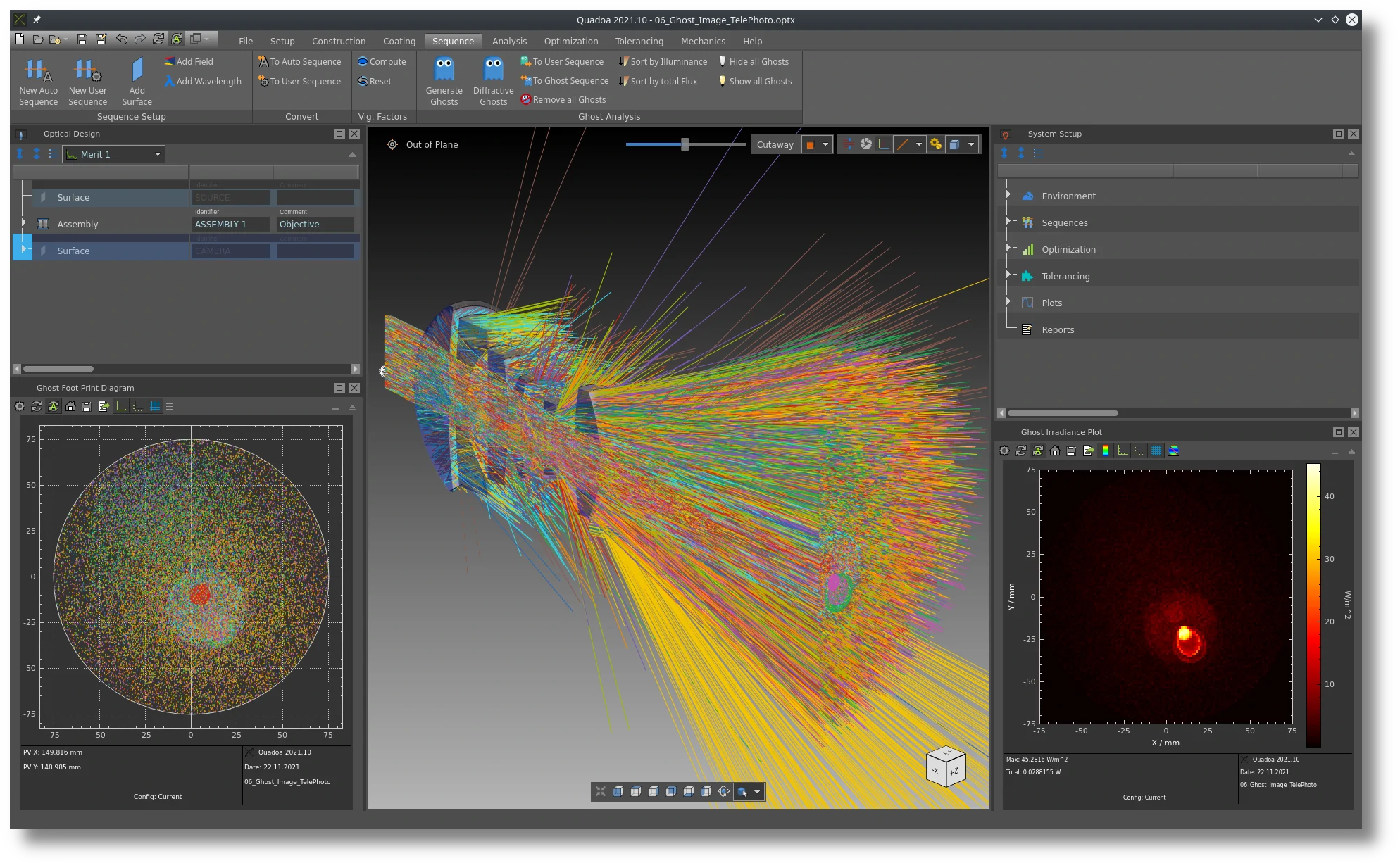
In-System Sequential Ghost Analysis |
|---|
|
|---|
| Ghost Wizard allows to easily generate any relevant ghost sequences directly inside the model. |
| Thousands of Lenses and Materials are implemented in the Lens- and Material Catalogs. |
|---|

Lens and Material Catalogs |
|---|
| Thousands of Lenses and Materials are implemented in the Lens- and Material Catalogs. |
|---|
Available for Windows and Linux |
|---|

|
|---|
| QUADOA® runs on Windows and Linux operating systems. |
|
|
|---|
|
|
|
|
|
|
|
|
|
|
|
|
|
|
|
|
|
|
|
|
|
|
|
|
|
|
|
|
|
|
|
|
|
|
|
|
|
|
|
|
|
|
|
|
|---|
|
|
|
|
|
|
|
|
|
|
|
|
|
|
|
|
|
|
|---|
|
|
|
|
|
|
|
|
|
|
|---|
|
|
|
|
|
|
|
|
|
|
|
|
|
|
|
|
|
|
|
|
|
|
|---|
|
|
|
|
|
|
|
|
|
|
|
|
|
|
|---|
|
|
|
|
|
|
|
|
|---|
|
|
|
|
|---|
|
|
|
|
|
|
|
|
|
|
|---|
|
|
|
|
|
|
|
|
|
|
|
|
|
|
|---|
|
|
|
|
|
|
|---|
|
|
|
|
|
|
|
|
|
|
|
|
|
|
|
|
|
|
|
|
|
|
|
|
|
|
|
|
|
|
|
|
|
|
|
|
|
|
|
|
|---|
|
|
|
|
|
|
|
|
|
|
|
|
|
|
|
|
|
|
|
|
|
|
|
|
|
|
|
|
|
|
|
|
|---|
|
|
|
|
|
|
|
|
|
|
|
|
|
|
|
|
|
|
|
|
|
|
|
|
|---|
|
|
|
|
|
|
|
|
|
|
|
|
|
|
|---|
|
|
|
|
|
|
|
|
|
|
|
|
|---|
|
|
|
|
|
|
|---|
|
|
|
|
|
|
|
|
|---|
|
|
|
|
|
|
|
|
|
|
|
|
|
|
|
|
|
|
|
|
|
|
|
|---|
|
|
|
|
|
|
|
|
|---|
|
|
|
|